Beginner / 2–3 hours
A little display with a lot to say
Sometimes your project doesn't need a whole screen. It needs a color, a moving light, or a quick way to tell you that something changed. Maybe that's a temperature display on your desk. Maybe it's a status indicator you can update from your phone. A handful of RGB LEDs can do a surprising amount of communicating!
The frustrating part can be getting all the pieces together. An external matrix needs a controller, power, wiring, and somewhere to put everything. PixelWing ESP32-S3 brings the controller and display onto one board, so you can spend more time making the display do something useful.
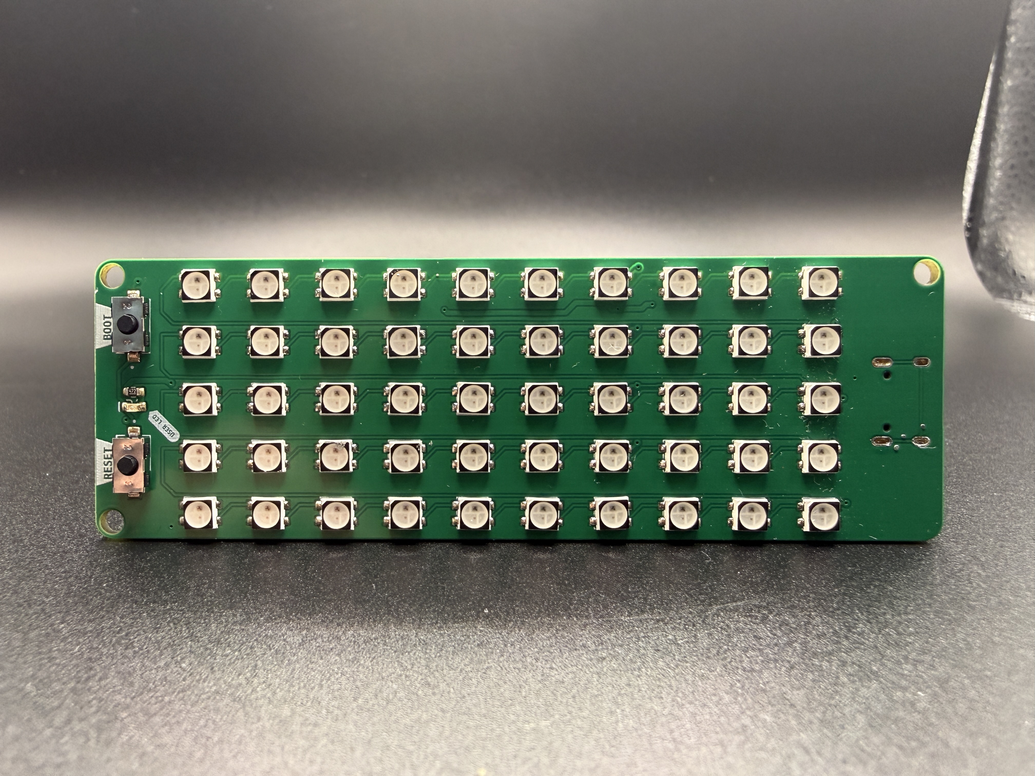
What does PixelWing give you?
- A 5 × 10 RGB matrix: 50 individually addressable pixels. Change the whole display, draw a small pattern, or give every LED its own color.
- An ESP32-S3: the microcontroller runs your program and provides onboard Wi-Fi. Your display can respond to something beyond the USB cable.
- USB-C power and data: connect to your computer to power the board and edit your CircuitPython program.
- A Qwiic / STEMMA QT compatible I2C connector: plug in a compatible 3.3 V sensor breakout without building a breadboard circuit first.
- CircuitPython support: save a Python file and see what happens. Adafruit's NeoPixel and LED Animation libraries give us a useful head start.
The matrix uses NeoPixel-compatible addressable RGB LEDs. Each LED receives its color through a chain, so our code sees a list of 50 pixels even though the board arranges them as a rectangle. We'll connect those two views in a moment.
The PixelWing ESP32-S3 product page has the board photos and feature overview.
Explore the open source design
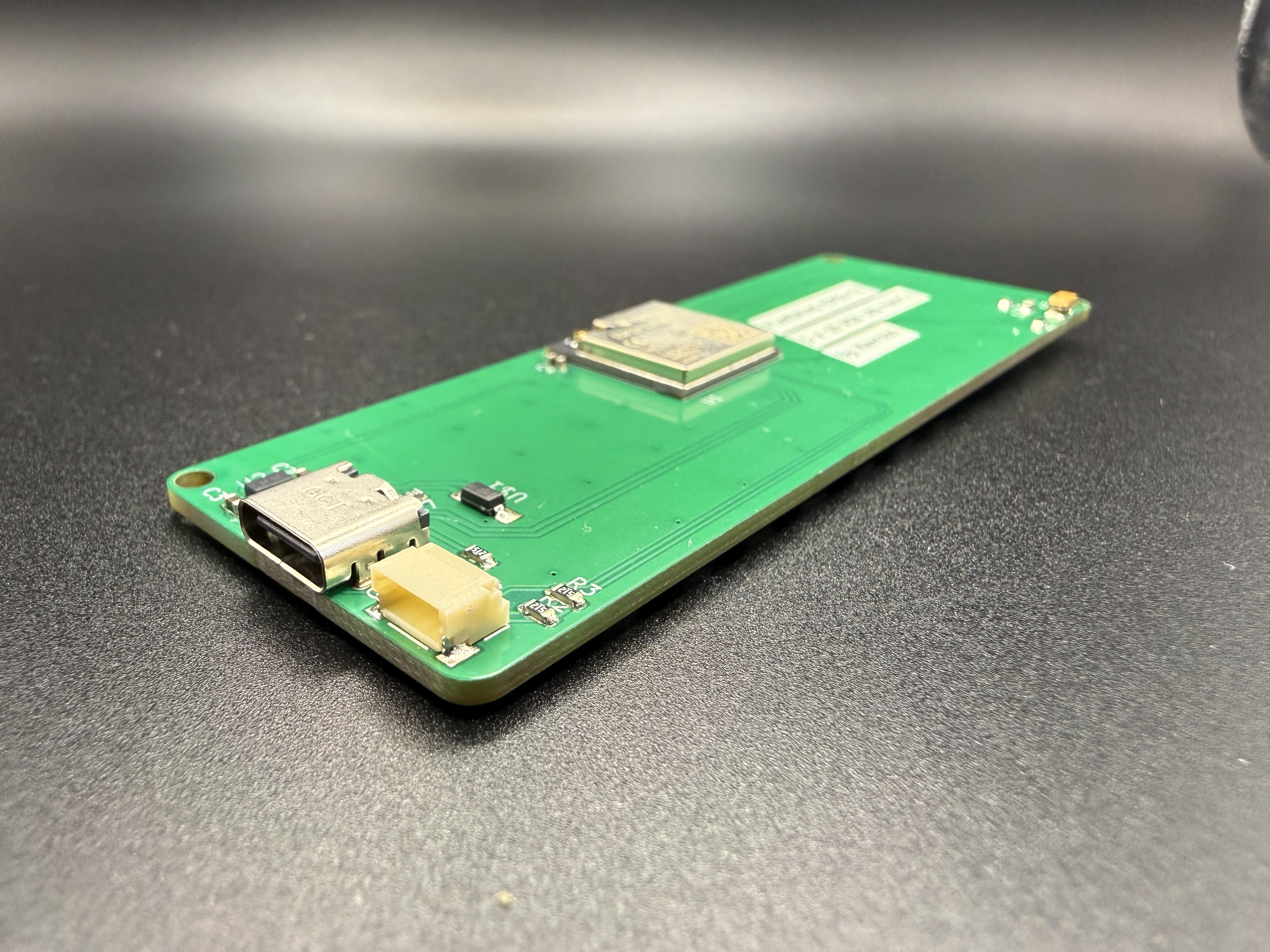
Want to see how PixelWing works underneath the examples? The PixelWing ESP32-S3 open source repository contains the board design and supporting documentation. You can follow a signal through the schematic, explore the PCB layout, or use the design as a starting point for your own hardware project.
- KiCad design files: the editable schematic and PCB layout show how the ESP32-S3, LED matrix, USB connector, and accessory connector fit together.
- Hardware reference: look up GPIO assignments and connector signals when writing code or adding an accessory.
- Manufacturing guide: find the production files and notes for making or modifying a board. Read the repository's license before sharing designs or manufacturing hardware.
You don't need KiCad or a copy of the repository to follow this guide. It's there when you want to look closer. If you find a problem or have a suggestion, open a GitHub issue with your board revision, firmware version, and enough detail for someone else to reproduce it.
The repository's firmware release and example status are separate from its hardware files. Check its getting-started notes and the firmware guidance below before looking for an installable CircuitPython image.
What we're going to build
We'll start with CircuitPython itself: where your code lives, how libraries work, and how to read an error. Then we'll make colors, move a pixel, and turn the LED chain into a coordinate system.
From there we'll use Adafruit's LED Animation library to build effects without writing every frame ourselves. We'll connect an I2C temperature sensor and make a display that responds to the room. Finally, we'll host a small web page on PixelWing and use a browser to change the matrix while the program runs.
Prefer Arduino? Jump straight to Program PixelWing with Arduino for the ESP32-S3 board definition, USB upload setup, and a complete matrix sketch. The other project pages use CircuitPython.
Work through the CircuitPython pages in order for your first project. After that, each project page has a complete replacement code.py, so you can come back to the part you need.
What you'll need
For the first four pages, bring a PixelWing ESP32-S3, a USB-C data cable, and a computer with a text editor and serial console. A charging-only cable can power LEDs while leaving you wondering where the board went.
For the sensor page, we'll use a BME280 I2C breakout with a Qwiic or STEMMA QT connector, plus the matching four-wire cable. The Wi-Fi page needs a 2.4 GHz network and a computer or phone on the same local network. PixelWing ESP32-S3 does not come with an antenna. Buy one separately for Wi-Fi or Bluetooth; the ESP32-S3-MINI-1U module uses an external antenna connector.
We'll keep matrix brightness at 0.05, or five percent, to start. That's a conservative starting setting, not a measured power limit. Fifty bright white LEDs can demand much more current than a few dim colored ones. If the board resets as it lights up, reduce brightness and check your USB cable and supply before continuing.
Choose an antenna
Look for a 2.4 GHz, 50 Ω antenna with a U.FL / IPEX MHF1 connector to match the module. Here are two ways to go:
- A small antenna that plugs straight in: Adafruit's 2.4 GHz mini flexible Wi-Fi antenna with U.FL connector, product 2308, is a simple starting option for a desk project.
- An antenna mounted outside an enclosure: use a 2.4 GHz RP-SMA Wi-Fi antenna with a matching Adafruit RP-SMA to U.FL adapter cable, product 852. The cable is an adapter, so buy the antenna too and check that its RP-SMA connector mates with the cable.
U.FL and the smaller W.FL / MHF3 or MHF4 connectors aren't interchangeable. Check the connector before ordering. Disconnect USB before fitting the antenna, align the tiny plug directly over the socket, and press gently straight down. Keep the antenna clear of metal and fit it before running wireless examples. USB programming and the LED-only projects don't need an antenna.
A quick note about firmware
This guide targets the ESP32-S3 PixelWing. The older ESP32-S2 version has different pin assignments. The S3 board definition provides board.NEOPIXEL on GPIO48, board.SDA on GPIO21, and board.SCL on GPIO47.
The CircuitPython projects assume PixelWing-specific CircuitPython is already installed. If your board doesn't show a CIRCUITPY drive, follow the firmware notes on the next page before trying the examples.