Beginner / 2–3 hours
Let a sensor change the display
Animations are fun, but a display gets more useful when it tells you something about the world. Let's connect a temperature sensor and turn the matrix into a little room-temperature indicator.
We'll use a BME280 breakout. It measures temperature, humidity, and pressure; for this project we'll use temperature to control both a bar and its color. You can adapt the same idea to light, motion, or air-quality sensors by changing the driver and the value you read.
Connect the I2C breakout
I2C is a shared bus with two signal lines: SDA carries data and SCL carries the clock. Devices have addresses so your program can talk to a particular sensor on those shared wires.
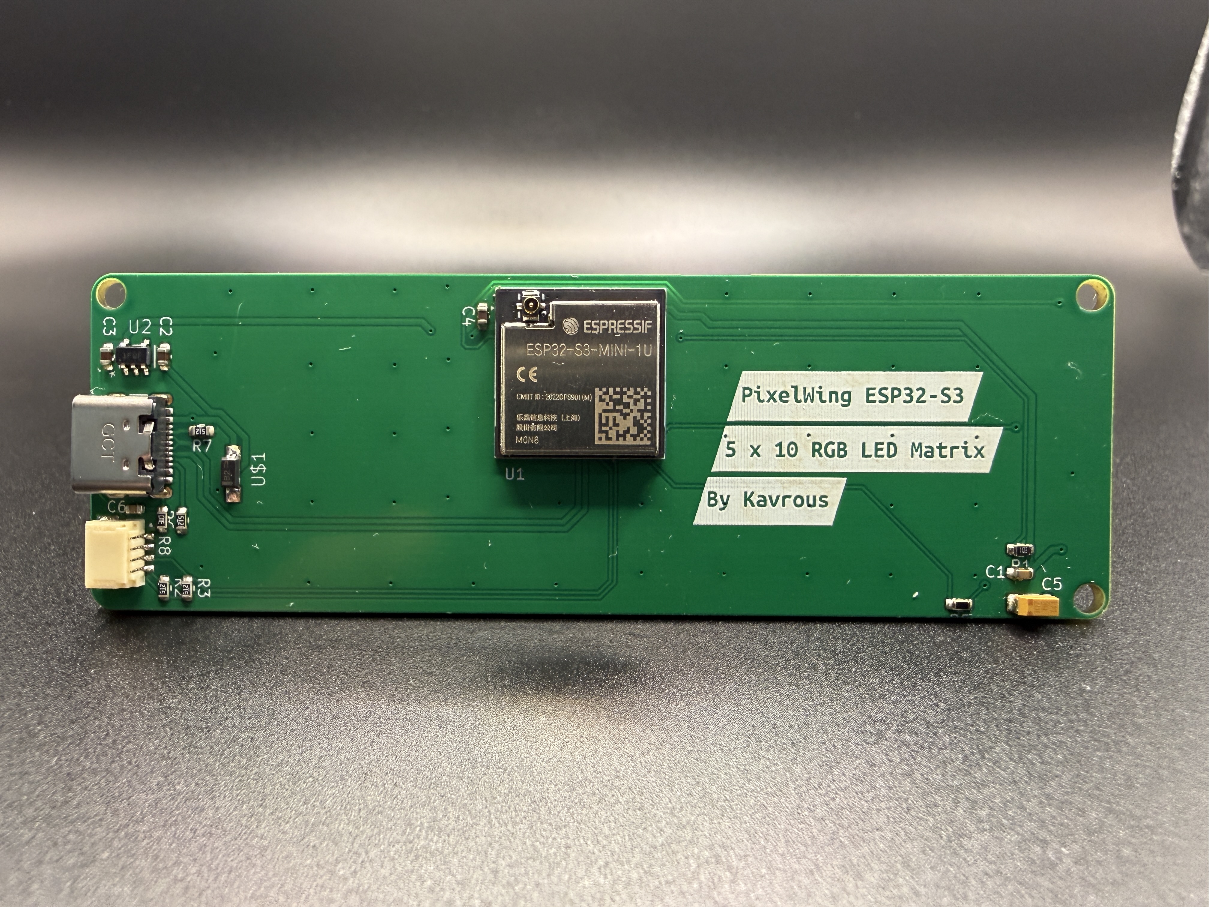
Disconnect USB, then connect a 3.3 V compatible BME280 Qwiic / STEMMA QT breakout to PixelWing's four-pin I2C connector with a matching cable. Reconnect USB after the cable is seated. A bare BME280 module with loose headers needs correctly wired connections; it isn't automatically a plug-in accessory.
| Connector signal | S3 connection | Purpose | | --- | --- | --- | | GND | Ground | Common reference | | 3.3 V | Accessory supply | Powers the breakout | | SDA | GPIO21 / board.SDA | Data | | SCL | GPIO47 / board.SCL | Clock |
This connector supplies 3.3 V, not 5 V. Use compatible accessories and check their pin order. Sensor boards often include pull-up resistors already; connecting many boards adds those resistors in parallel and can affect the bus. Start with one short cable and one sensor.
Find the sensor before asking for a measurement
This complete scanner needs only built-in modules. Save it as code.py and open the serial console:
import time
import board

i2c = board.I2C()

while not i2c.try_lock():
    time.sleep(0.01)
try:
    print("I2C addresses:", [hex(address) for address in i2c.scan()])
finally:
    i2c.unlock()
board.I2C() selects GPIO47 for SCL and GPIO21 for SDA on the S3 definition. With firmware that exposes raw GPIO names, the explicit equivalent is busio.I2C(board.IO47, board.IO21) after importing busio. Create one bus object and share it with drivers; don't create both versions on the same pins.
A BME280 commonly appears at 0x77 or 0x76, depending on the breakout's address setting. An address acknowledges that a device is present; it doesn't prove which sensor model it is. A BMP280, for example, needs a different driver.
The scanner locks the bus while it probes addresses and releases the lock in finally, even if scanning raises an error. Drivers manage locking for their own transactions, so don't keep this manual lock around when creating the sensor. CircuitPython's I2C reference explains the bus methods.
Turn temperature into a bar
Install neopixel and its dependencies, plus the adafruit_bme280, adafruit_bus_device, and adafruit_register folders from the matching bundle. Replace the scanner with this complete code.py:
import time
import board
import neopixel
from adafruit_bme280 import basic as adafruit_bme280

WIDTH = 10
HEIGHT = 5
LOW_C = 18.0
HIGH_C = 30.0
SENSOR_ADDRESS = 0x77  # Change to 0x76 if that is your scanned address.

pixels = neopixel.NeoPixel(
    board.NEOPIXEL, WIDTH * HEIGHT, brightness=0.05,
    auto_write=False, pixel_order=neopixel.GRB
)
i2c = board.I2C()
sensor = adafruit_bme280.Adafruit_BME280_I2C(i2c, address=SENSOR_ADDRESS)

def xy(x, y):
    return y * WIDTH + x

while True:
    temperature = sensor.temperature
    fraction = (temperature - LOW_C) / (HIGH_C - LOW_C)
    fraction = max(0.0, min(1.0, fraction))
    lit_columns = int(fraction * WIDTH + 0.5)
    color = (int(255 * fraction), 0, int(255 * (1.0 - fraction)))

    pixels.fill((0, 0, 0))
    for x in range(lit_columns):
        for y in range(HEIGHT):
            pixels[xy(x, y)] = color
    pixels.show()
    print("Temperature:", temperature, "C; columns:", lit_columns)
    time.sleep(0.5)
Use your verified xy() mapping here too. The BME280 examples show the driver setup and additional measurements.
At 18 °C or below, the bar is empty. Around 24 °C, half the columns glow purple. At 30 °C or above, all ten columns glow red. Between those points, the bar grows and shifts from blue toward red. These are display choices, not health or equipment thresholds.
Subtracting LOW_C moves the start of our range to zero. Dividing by HIGH_C - LOW_C turns the reading into a fraction. Clamping with min and max keeps the result between zero and one, so a warmer room can't produce an out-of-range pixel index or RGB channel.
Try setting LOW_C and HIGH_C around the temperature printed in your console, keeping HIGH_C greater than LOW_C. Gently warming the breakout with a nearby hand should change the reading over time. The sensor also responds to heat from nearby electronics; keep it away from the matrix if you want a better estimate of room temperature.
If the sensor doesn't answer
An empty scan usually means a connection, power, or wiring problem. Unplug power before reseating the cable. If the address appears but driver initialization fails, check the selected address and confirm the breakout really is a BME280. If the display stays empty, read the printed temperature: it may simply be below the range you chose.
Once this works, try sensor.relative_humidity with a 0–100 scale, or change the display into a simple blue/amber/red status indicator. The pattern stays the same: read a value, decide what it means, draw the result.